Firing Room - Area B

Area B
Most of the control panels that I have photographed come from Area B. This Area was divided into 5 rows. Specific sections were assigned to the various stages of the launch vehicle, ground support equipment (e.g., fuel loading systems, power supplies, etc.), and in-flight control of the launch vehicle.
The prime contractors for the various stages manned the consoles for their stages. In period photos, you will see Boeing personnel at the S-IC consoles, Rockwell at those for the S-II, Douglas at those for the S-IVB, and Chrysler at those for the S-IB.

Since most period photos of the Firing Rooms were taken from Area A, the first two rows of Area B (rows A and B) were most easily visible in the photos. This makes it relatively straightforward to pinpoint the location of panels supporting the S-IC, S-II, and S-IVB stages. Panels for other functions are harder to identify in the FR photos, so we must use other methods to locate them.
The Apollo Firing Rooms were divided into Areas (A through F), with lettered Rows and numbered Console locations. This page focuses on Area B, which housed the primary test, checkout, monitoring, and control functions for the launch vehicle.
EXAMPLE: Locating by “Disposition” sticker
The surplussed control panels that ended up in Charlie Bell’s collection had, in many cases, stickers attached to the face of them that indicated that they were for “Disposition.” These stickers also noted the location of the panel by Area, Row, and Rack (console number). In many cases, these stickers are too faded to read, but some of them are still legible.
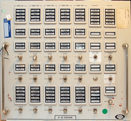
Contrast-enhanced close-up of the Disposition sticker on this panel. It shows that the panel was from Area/Row BA, Rack 6. As expected, this corresponds to the S-IC row of Area B, as indicated in the Firing Room layout diagram.

S-IC FUEL SYSTEM panel. The Disposition sticker is in the lower center, just above the lowest meter. (Scott Unterberg collection)

EXAMPLE: Locating by matching key features of the panel
Most panels had a unique layout of indicators, meters, and switches. The layouts are relatively easy to spot on photographs of the Firing Room, provided the resolution is high and a large portion of the panel is visible.
The various ENGINE DEFLECTION panels have very large meters, which make them easy to spot in photos of the Firing Room, even though they are near the back of Area B.


S-IVB ENGINE DEFLECTION
S-II ENGINE DEFLECTION

S-IC ENGINE DEFLECTION

Section of a photo of Firing Room 1 in January 1967 with the three ENGINE DEFLECTION panels highlighted. They are seen in Row D (Flight Control), positions 11, 12, and 15.
EXAMPLE: Putting it all together
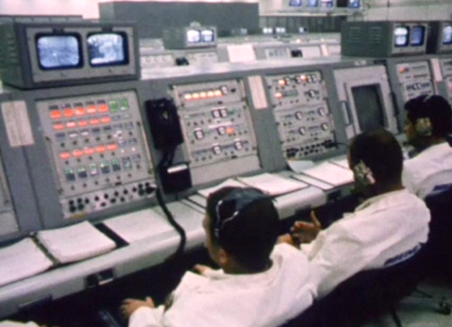
Sometimes it takes a variety of clues and logical progression to make a positive identification. The photo below is a still from a film clip of the Apollo 8 Countdown Demonstration Test (film courtesy of www.footagevault.com). Where is this located in the Firing Room, and what panels are represented in the photo?
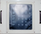
First, the engineers are wearing Boeing patches on their backs, so this is likely a section related to the S-IC stage. Pattern matching on the features of the panels that are clearly seen indicate that they are (from left), S-IC ENGINE, S-IC CONTROL AND PURGE (in the lower position on the console), and S-IC GROUND PNEUMATICS (also in the lower position of its console). So, this is likely Area B, Row A, left side (i.e., the S-IC section). Looking at the layout of Area B, we see that there is a CRT at console 5. (The CRT is the big rectangular screen toward the right of the image below.) Therefore, the S-IC ENGINE panel is in console 2, the S-IC CONTROL AND PURGE is in console 3, and the S-IC GROUND PNEUMATICS panel is in console 4. These positions in fact match up with the disposition stickers on the panels.


S-IC GROUND PNEUMATICS panel (Scott Unterberg collection)
S-IC CONTROL AND PURGE panel (Ward collection)

S-IC ENGINE panel
(Ward collection)


CRT (KSC Saturn V Visitors Center)